- 您现在的位置:买卖IC网 > Sheet目录2007 > MAX11049ECB+ (Maxim Integrated Products)IC ADC 16BIT PAR 250KSPS 64TQFP
MAX11047–MAX11049/MAX11057–MAX11059
4-/6-/8-Channel, 16-/14-Bit,
Simultaneous-Sampling ADCs
______________________________________________________________________________________
15
Input Range and Protection
The full-scale analog input voltage is a product of the
reference voltage. For the devices, the input is unipolar
in the range of:
In external reference mode, drive VREFIO with a 3.0V to
4.25V source, resulting in a full-scale input range of
3.662V to 5.188V, respectively.
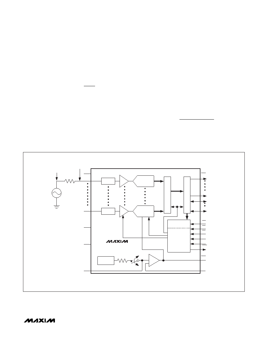
All analog inputs are fault-protected up to ±20mA. The
devices include an input clamping circuit that activates
when the input voltage at the analog input is above
(VAVDD + 300mV) or below -300mV. The clamp circuit
remains high impedance while the input signal is within
the range of 0V to +VAVDD and draws little to no cur-
rent. However, when the input signal exceeds the range
of 0V to +VAVDD, the clamps begin to turn on.
Consequently, to obtain the highest accuracy, ensure
that the input voltage does not exceed the range of 0V
to +VAVDD.
To make use of the input clamps, connect a resistor
(RS) between the analog input and the voltage source
to limit the voltage at the analog input so that the fault
current into the devices does not exceed ±20mA. Note
that the voltage at the analog input pin limits to approxi-
mately 7V during a fault condition so the following
equation can be used to calculate the value of RS:
where VFAULT_MAX is the maximum voltage that the
source produces during a fault condition.
R
VV
mA
S
FAULT MAX
=
_
7
20
0
50
4 096
to
V
x
REFIO
+
.
MAX11047/MAX11048/MAX11049/
MAX11057/MAX11058/MAX11059
CLAMP
S/H
16-/14-BIT ADC
CLAMP
S/H
16-/14-BIT ADC
REF
BUF
CONFIGURATION
REGISTERS
INTERFACE
AND
CONTROL
BANDGAP
REFERENCE
8x
16-/1
4-BIT
REGISTERS
BIDIRECTIONAL
DR
IVERS
CH0
SOURCE
AVDD
AGNDS
*CONNECTED INTERNALLY ON THE TQFN PARTS
**MAX11047/MAX11048/MAX11049
MAX11049/MAX11059
AGND
CH7
DB15**
DB0/CR0
DB3/CR3
DB4
EOCb
SHDN
CONVST
CSb
RDb
WRb
DGND
DVDD
RDC
RDC_SENSE*
REFIO
INT REF
10k
EXT REF
RS
INPUT
SIGNAL
PIN
VOLTAGE
Figure 1. Required Setup for Clamp Circuit
发布紧急采购,3分钟左右您将得到回复。
相关PDF资料
MAX1104EUA+
IC CODEC 8BIT 8-UMAX
MAX11100EUB+
IC ADC 16BIT SRL 200KSPS 10UMAX
MAX11101EUB+
IC ADC 14BIT SRL 200KSPS 10UMAX
MAX11102AUB+
IC ADC 12BIT SPI/SRL 10UMAX-EP
MAX1111CPE+
IC ADC 8BIT LP 16-DIP
MAX1113CPE+
IC ADC 8BIT LP 16-DIP
MAX1116EKA+T
IC ADC 8BIT SERIAL SOT23-8
MAX11201BEUB+T
IC ADC 24BIT SRL 13.75SPS 10UMAX
相关代理商/技术参数
MAX11049ECB+T
功能描述:模数转换器 - ADC 16Bit 8Ch Simult Sampling RoHS:否 制造商:Texas Instruments 通道数量:2 结构:Sigma-Delta 转换速率:125 SPs to 8 KSPs 分辨率:24 bit 输入类型:Differential 信噪比:107 dB 接口类型:SPI 工作电源电压:1.7 V to 3.6 V, 2.7 V to 5.25 V 最大工作温度:+ 85 C 安装风格:SMD/SMT 封装 / 箱体:VQFN-32
MAX11049ETN+
功能描述:模数转换器 - ADC 16Bit 8Ch Simult Sampling
RoHS:否 制造商:Texas Instruments 通道数量:2 结构:Sigma-Delta 转换速率:125 SPs to 8 KSPs 分辨率:24 bit 输入类型:Differential 信噪比:107 dB 接口类型:SPI 工作电源电压:1.7 V to 3.6 V, 2.7 V to 5.25 V 最大工作温度:+ 85 C 安装风格:SMD/SMT 封装 / 箱体:VQFN-32
MAX11049ETN+T
功能描述:模数转换器 - ADC 16Bit 8Ch Simult Sampling RoHS:否 制造商:Texas Instruments 通道数量:2 结构:Sigma-Delta 转换速率:125 SPs to 8 KSPs 分辨率:24 bit 输入类型:Differential 信噪比:107 dB 接口类型:SPI 工作电源电压:1.7 V to 3.6 V, 2.7 V to 5.25 V 最大工作温度:+ 85 C 安装风格:SMD/SMT 封装 / 箱体:VQFN-32
MAX1104EUA
制造商:Maxim Integrated Products 功能描述:
MAX1104EUA+
功能描述:ADC / DAC多通道 8-Bit CODEC RoHS:否 制造商:Texas Instruments 转换速率: 分辨率:8 bit 接口类型:SPI 电压参考: 电源电压-最大:3.6 V 电源电压-最小:2 V 最大工作温度:+ 85 C 安装风格:SMD/SMT 封装 / 箱体:VQFN-40
MAX1104EUA+T
功能描述:ADC / DAC多通道 8-Bit CODEC RoHS:否 制造商:Texas Instruments 转换速率: 分辨率:8 bit 接口类型:SPI 电压参考: 电源电压-最大:3.6 V 电源电压-最小:2 V 最大工作温度:+ 85 C 安装风格:SMD/SMT 封装 / 箱体:VQFN-40
MAX1104EUA+TW
功能描述:ADC / DAC多通道 8-Bit CODEC +2.7V to +5.5V Single Supply RoHS:否 制造商:Texas Instruments 转换速率: 分辨率:8 bit 接口类型:SPI 电压参考: 电源电压-最大:3.6 V 电源电压-最小:2 V 最大工作温度:+ 85 C 安装风格:SMD/SMT 封装 / 箱体:VQFN-40
MAX1104EUA+W
功能描述:ADC / DAC多通道 8-Bit CODEC +2.7V to +5.5V Single Supply RoHS:否 制造商:Texas Instruments 转换速率: 分辨率:8 bit 接口类型:SPI 电压参考: 电源电压-最大:3.6 V 电源电压-最小:2 V 最大工作温度:+ 85 C 安装风格:SMD/SMT 封装 / 箱体:VQFN-40